THE GHIST:
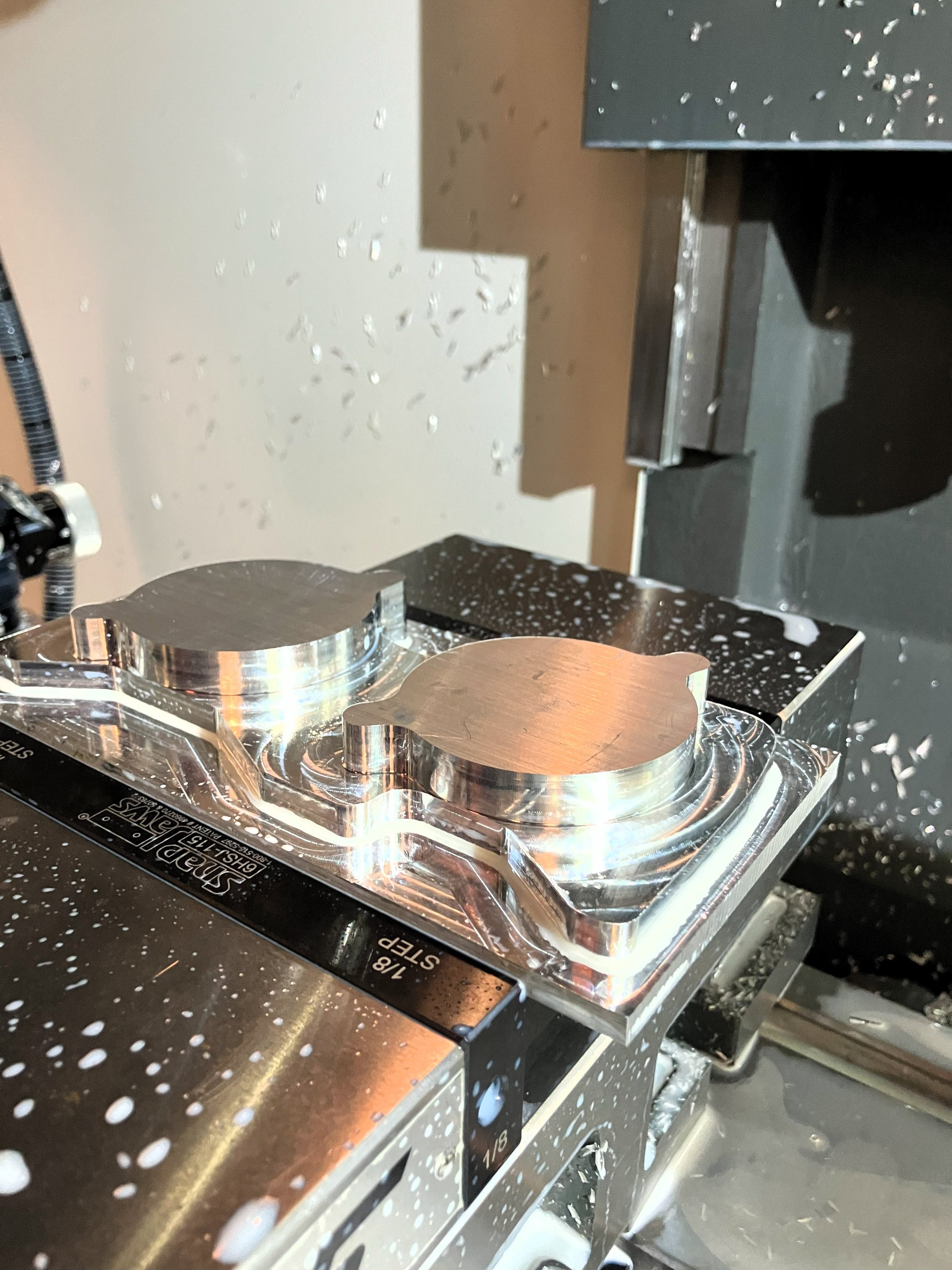
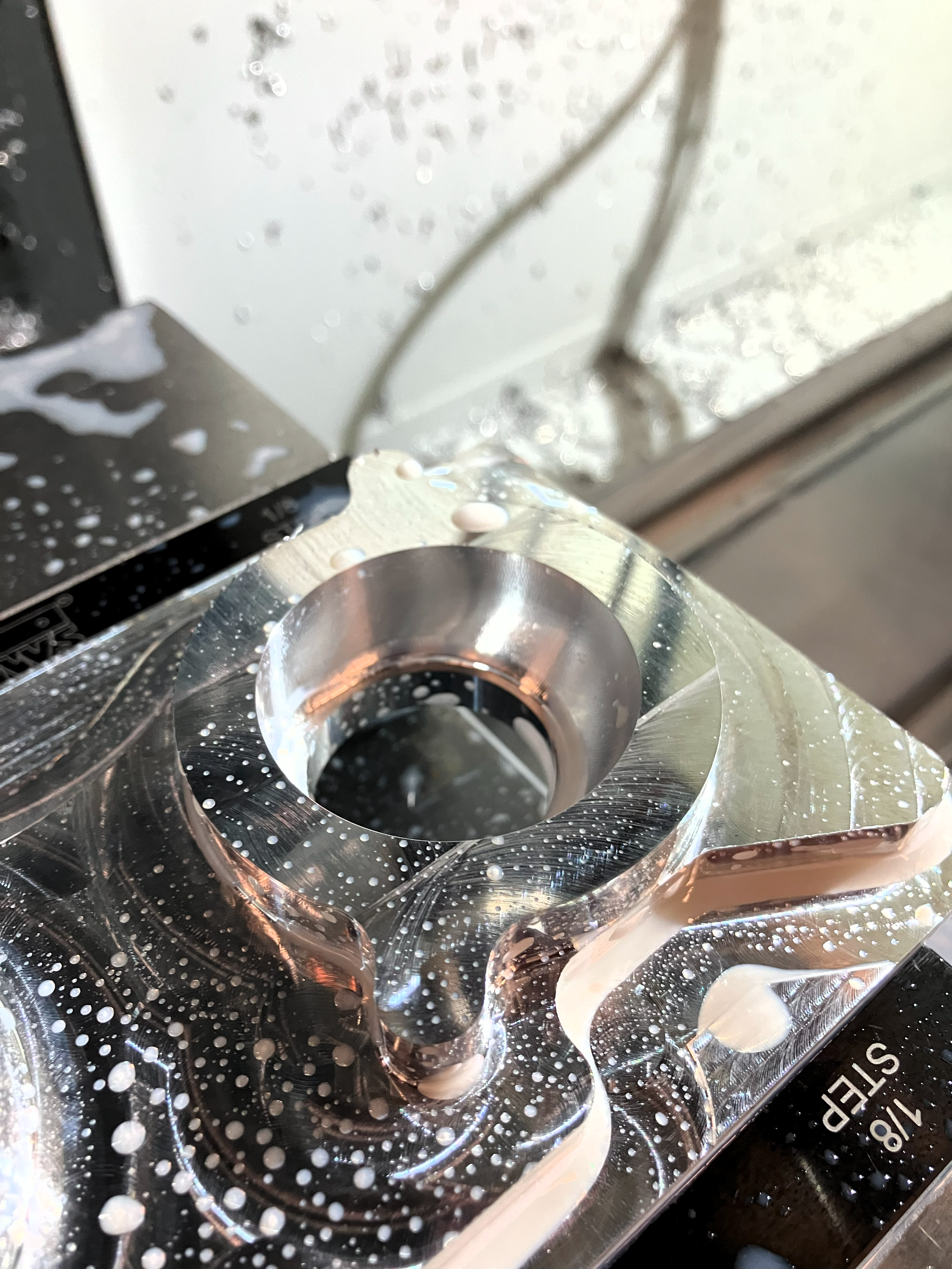
Final project for an introductory course on CNC operation.
A bespoke engine component designed to be used on my project car.
Done in collaboration with and under the supervision of CTMMA shop tech Aidan La Honta
“WHAT ARE THOSE?”
On a normal car, the engine receives air from a single plenum (throttle body), after which the air is divided among each cylinder. This is used from factory due to having less moving parts and being easier to tune.
Most importantly (to me), they look and sound absolutely wicked.
Individual throttle bodies will be most often installed on race cars, but also come on some cars from the factory- such as Ferrari, Alfa Romeo, BMW, as well as select Hondas, Nissans, and Toyotas.
Seems like a perfect fit for a run-down 80s Nissan, no?
My 1986 Nissan 200SX (Silvia, S12)
RAPID PROTOTYPING
DESIGN FOR MANUFACTURING
FUSION CAD + CAM
CNC SETUP + OPERATION HAAS TM-2 (NGC + WIPS)
KEYSHOT
This not only allows for a larger volume of air to be delivered to each cylinder, but also allows for precise tuning of the airflow reaching each cylinder.
If set up properly, one should be able to achieve more power and a more responsive throttle.
The familiar view under the hood of a Subaru. Note the large pipe stretching between the bottom right to the center of the engine, after which it splits off into four smaller ones. The throttle body is located right before that split.
On certain performance oriented engine setups, each cylinder is paired to its own (individual) throttle body.
VISIONS OF A MADMAN
I had recently finished rebuilding the engine, and the intake was giving me trouble. I figured I’d seize the opportunity to redesign the adapter plate while I had access to a mill at DVC.
A double overhead cam CA18 out of a 1989 Nissan Pulsar, recently refreshed. Decorated with 4 throttle bodies off of a 1991 Toyota “Silvertop” 4A-GE engine
SCRAP YARD MECHANIC
Adapters drilled out of blocks of composite.
ITBs for cylinders 1 and 2 mounted to the adapter.
Adapters are difficult to mount to the manifold, and the ITBs are difficult to mount to the adapter.
Mounting hardware is difficult to access and use reliably.
Porting between the ITB and manifold is rough and could be restricting airflow.
Mating surfaces need additional sealing with silicone to prevent vacuum leaks within the system.
Not the most aesthetically pleasing component.
A rough concept made of composite stock.
Practical enough, but somewhat inconvenient in its design.
MEASURE ONCE, CUT SEVEN TIMES.
CAD + CAM
ITB mounting points.
A whole lot of painters tape and a few pounds of wasted PETG filament later, the components finally aligned.
After getting the two profiles to align, it was time to blend the contours with a loft and turn the features into a solid before proceeding with the CAM.
No post-processing required after CNC operations.
Achieve all complex geometry (namely the compound curve undercuts) with just two set-ups.
Design to include mounting hardware and adequate clearance for components.
Given my constraints, I made out to meet a few objectives with the design.
First iteration of a 3D Printed mock-up, for test fitting.
Adaptive clearing 3D tool path operation.
Manifold-side features.
Final model with lofted boundaries. Ready for CAM.
With literature on the vintage Nissan engine components being so hard to come by, I had to do a lot of measuring by hand.
The ITB parameters were significantly easier to reference due to the strong cult following behind 80s Corollas.


